 ar
ar bg
bg hr
hr cs
cs da
da nl
nl fi
fi fr
fr de
de el
el hi
hi it
it ko
ko no
no pl
pl pt
pt ro
ro ru
ru es
es sv
sv tl
tl iw
iw id
id lv
lv lt
lt sr
sr sk
sk sl
sl uk
uk vi
vi et
et hu
hu th
th tr
tr fa
fa ms
ms hy
hy ka
ka ur
ur bn
bn mn
mn ta
ta kk
kk uz
uz ku
ku
load cell wiring diagram
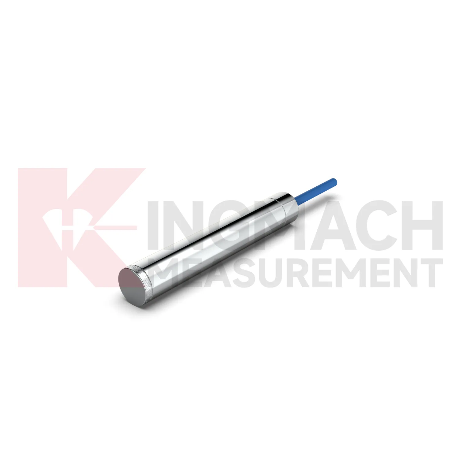
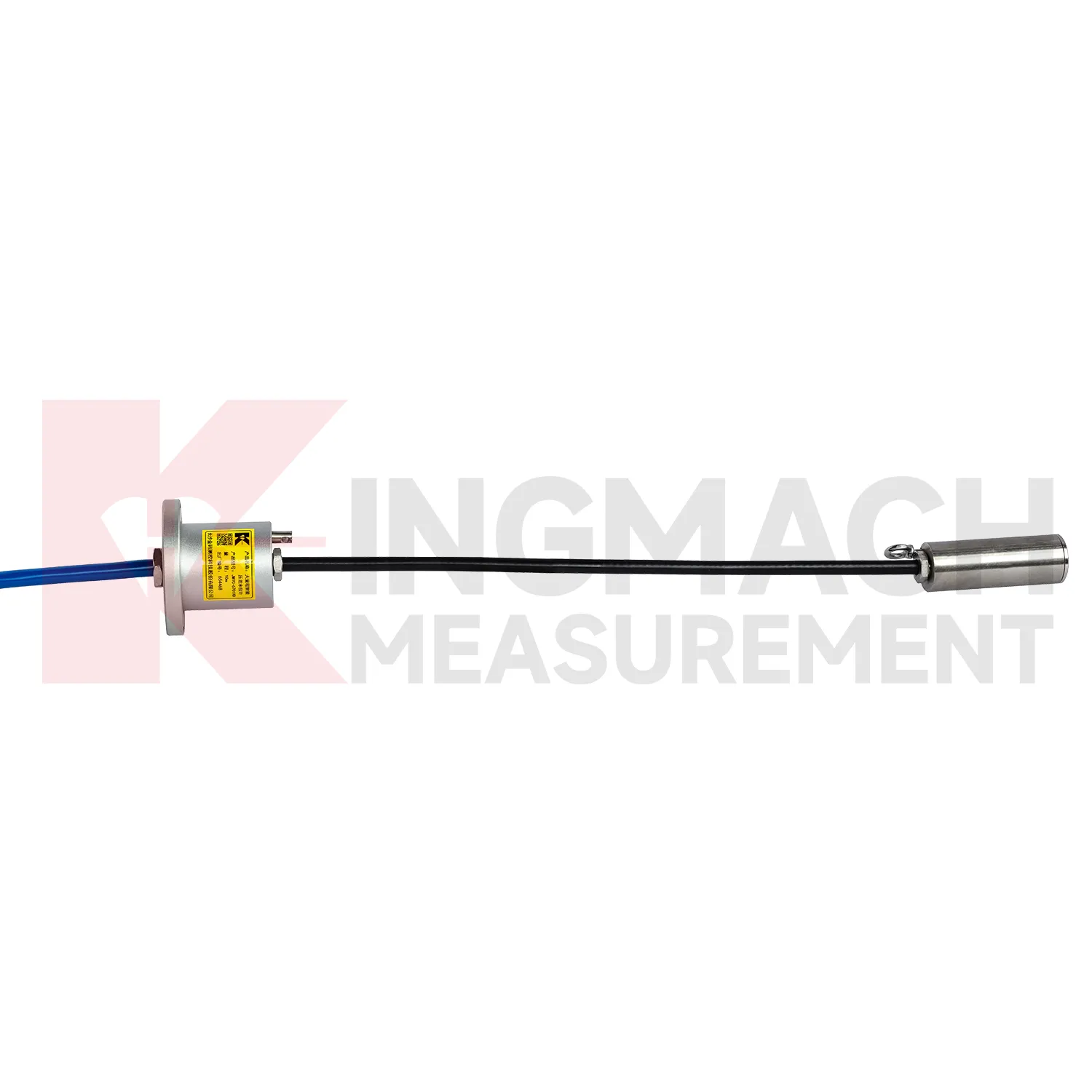
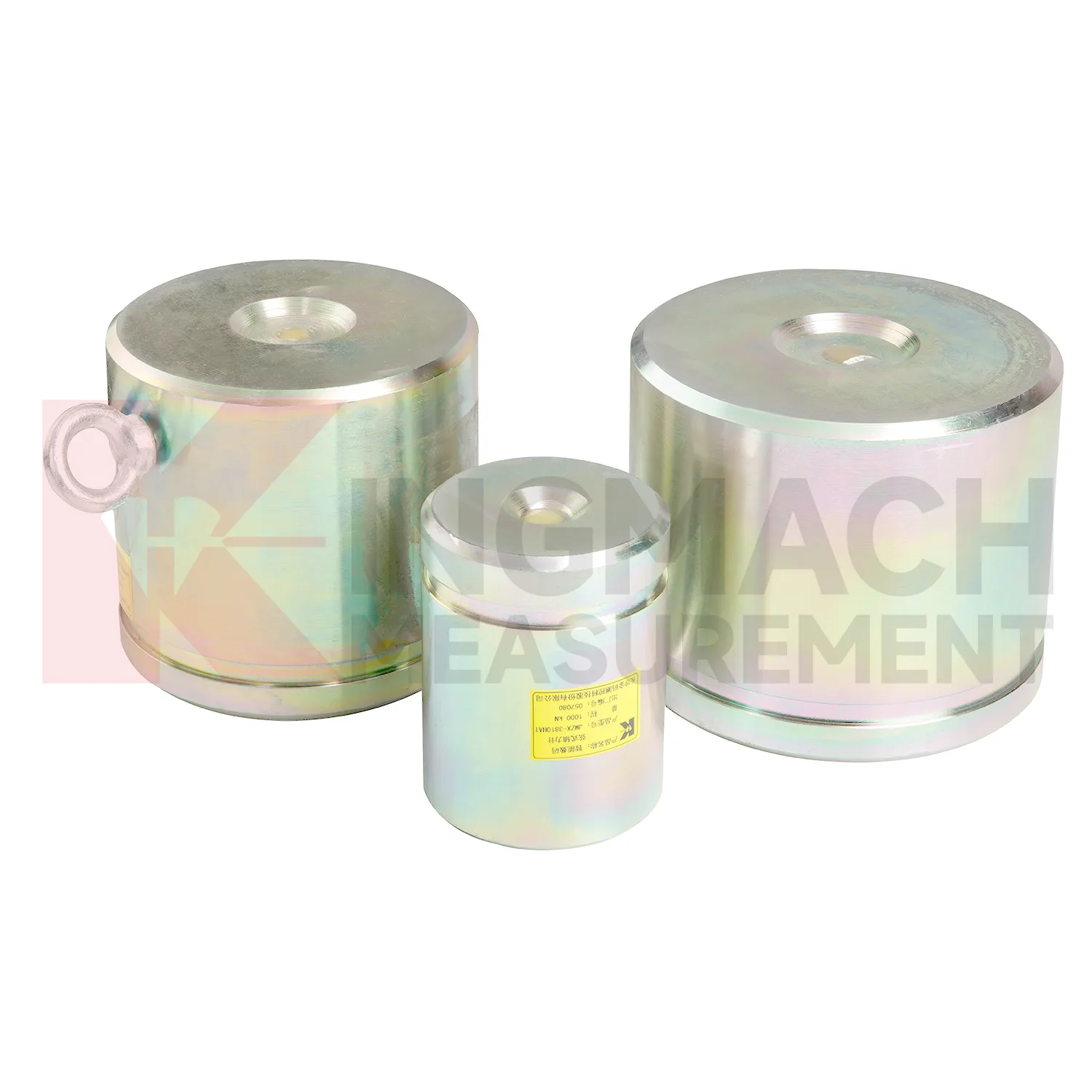
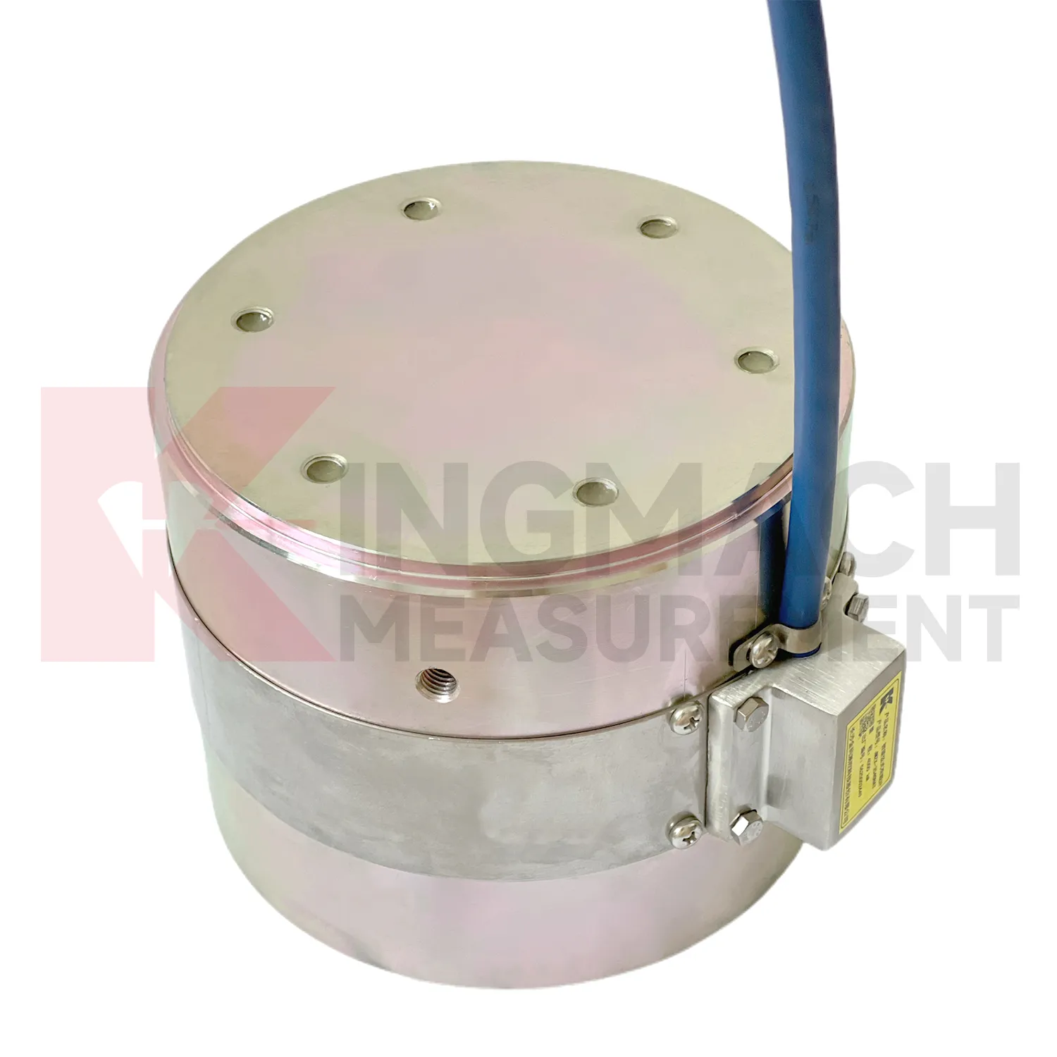
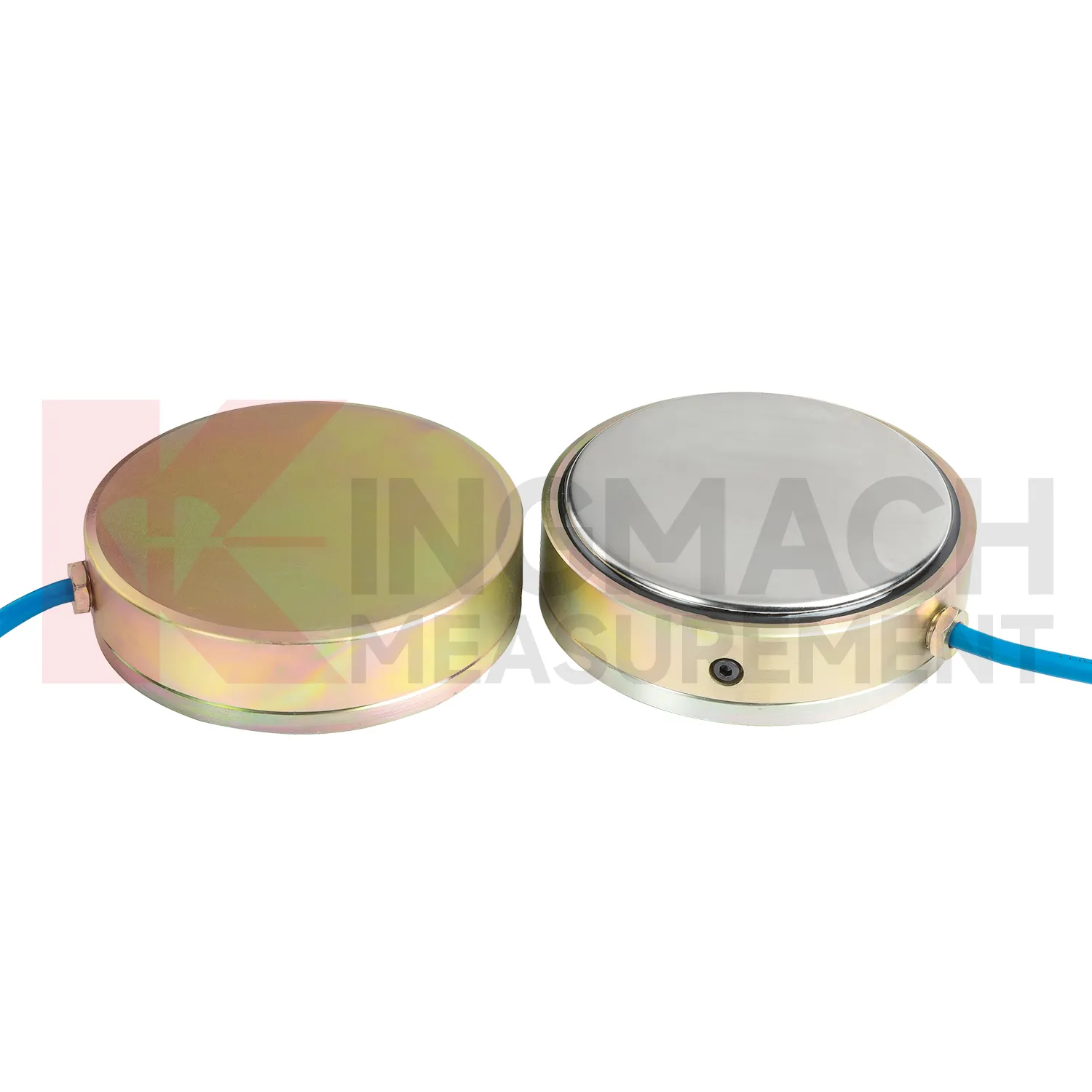
Kingmach load cell wiring diagram for axial force monitoring addresses a common site problem: steel supports in deep foundation pits and tunnels can gain load quickly as excavation progresses. The JMZX-38XXHAT axial force load meter is listed in 200 kN, 500 kN, 1000 kN, 2000 kN, and 3000 kN ranges, with 0.1 kN or 1 kN sensitivity and 0.5%FS accuracy. Its product page lists a 1 MPa waterproof rating, automatic temperature correction, imported high strength steel wires, and direct axial force display in kN rather than only vibrating wire frequency. Claw type installation accessories are provided to help field placement. These features make the product relevant for temporary support monitoring, tunnels, tailings ponds, bridges, buildings, railways, transport, hydropower, and dams. Kingmach also notes that many axial force meters are customized, with model, range, and dimension confirmed at order. That matters when the support diameter, bearing plate thickness, and available clearance are already fixed by the construction design. The brand information also points to practical supply details, including Changsha origin, project use across transport and hydropower works, readout compatibility, and packaging for precision sensors. For engineering buyers, these details help connect catalog parameters with delivery, calibration, installation, and later service expectations.
Application of load cell wiring diagram
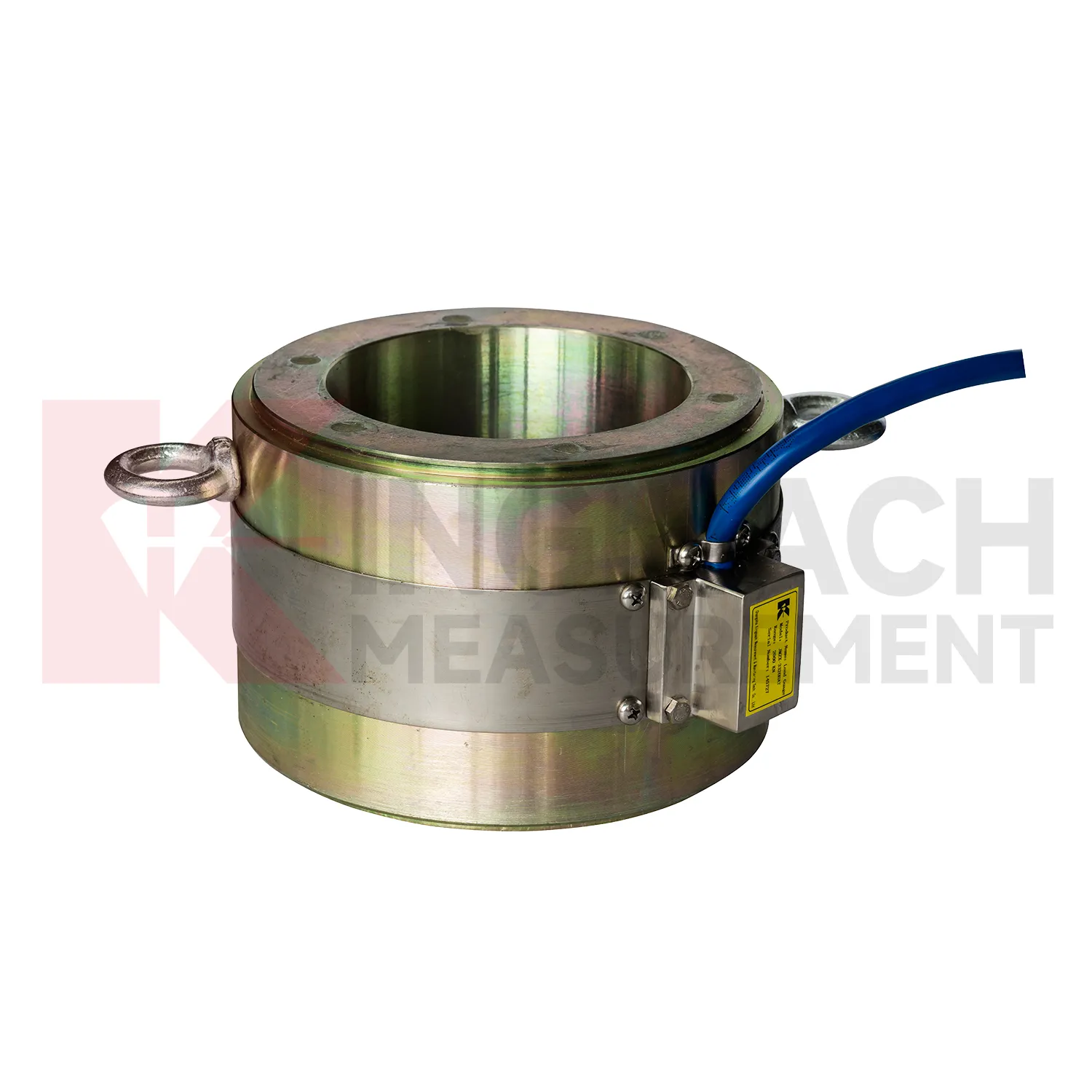
In industrial force testing and heavy equipment monitoring, load cell wiring diagram can be applied to presses, jacks, lifting frames, cranes, test benches, fixtures, and custom loading rigs. The pain point is repeatability. A test may pass once, but the owner needs to know whether the next test used the same loading path, sensor range, and calibration basis. Kingmach solid load cells provide high capacity force measurement up to 10000 kN with 0.5%FS precision, while hollow load cells cover 500 kN to 8000 kN and can store 800 measurement records on smart models. Axial force meters provide 200 kN to 3000 kN ranges and direct kN display. These features suit both site acceptance testing and repeated equipment checks. Installation should control centering, bearing plate flatness, side loading, cable strain relief, and zero reading before load is applied. Data becomes stronger when the report records operator, fixture condition, load stage, temperature, and any overload event. For test benches, repeatability also depends on fixture stiffness, alignment, and loading rate. A high accuracy sensor cannot correct a poor mechanical setup, so maintenance should include the test frame and not only the measuring element. The monitoring plan should also define who reviews abnormal data and how quickly a field check must follow a confirmed alarm.
The future of load cell wiring diagram
Future load cell wiring diagram use will depend on cleaner data pipelines, not only stronger metal parts. Kingmach's smart load cell features, including digital output, long distance transmission, anti-interference performance, temperature correction, and stored parameters, already point toward connected monitoring. In the next few years, more projects are likely to use edge acquisition units that check whether a reading is plausible before it reaches the platform. A sudden force jump can be compared with temperature, cable condition, nearby displacement, and recent construction events. AI based warning tools may help sort routine fluctuation from patterns that deserve inspection, but they will only work when the instrument record is consistent. That places more value on channel naming, calibration certificates, zero checks, installation photos, and maintenance logs. The product direction is therefore practical: robust sensing at the point of load, reliable transmission from difficult sites, and software that helps engineers review trends without losing the original measurement context.
Care & Maintenance of load cell wiring diagram
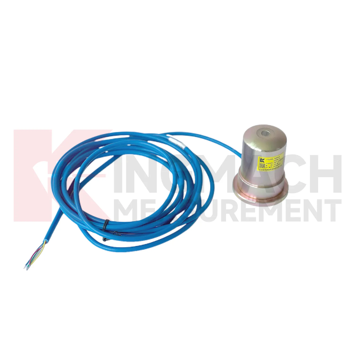
For load cell wiring diagram installed in foundation pits or tunnels, the maintenance routine must fit a fast changing site. Axial force meters may cover 200 kN to 3000 kN with 0.5%FS accuracy and direct kN display, while earth pressure cells may cover 0.3 MPa to 8 MPa with 0.001 MPa resolution. During installation, confirm that steel support surfaces have enough thickness and strength, and add buffer plates where stress concentration is possible. Protect the sensor body and cable from equipment impact, cutting, concrete splash, and standing water. During excavation, check readings after each major stage rather than waiting for a fixed calendar date. If a channel becomes unstable, inspect the cable route, connector, readout, and temperature condition first. Long term points should have waterproof labels, photo records, and clear channel mapping. Sudden changes should be compared with wall movement, settlement, water pressure, and site work before any conclusion is recorded.
Kingmachload cell wiring diagram
load cell wiring diagram supports decisions that are too important to leave to visual inspection alone. A bridge anchor plate may look unchanged while force redistributes between strands. A deep excavation support may still be straight while axial load rises. A pile test may appear steady while the loading system introduces eccentric force. Kingmach's load monitoring range gives engineers several instrument formats for these different questions, including hollow, solid, axial force, and pressure related products. The field value depends on repeatability. A reading taken today must be comparable with the first stable reading, the next load stage, and the record after temperature changes. That is why calibration coefficients, zero values, cable labels, installation photos, and compatible readouts matter. When all of those details are controlled, force monitoring becomes a practical inspection record rather than a one-time test result. That discipline turns a single load point into evidence that can be reviewed months later.
FAQ
Q: When is a solid load cell wiring diagram more suitable than a hollow type? A: Solid models are commonly used for compression load, pile load testing, bridge pier support checks, and heavy bearing capacity measurement. Q: What specifications does the Kingmach solid load cell list? A: The JMZX-35XXHAT line lists 1000 kN to 10000 kN ranges, 0.1 kN resolution, 0.5%FS precision, and -30°C to 80°C working temperature. Q: How much overload margin is listed? A: Product information lists 20 to 50%F.S. range overload and 300 to 400%F.S. failure overload. Q: What installation errors affect accuracy? A: Eccentric loading, uneven bearing plates, side load, cable pulling, and missing zero records can all distort results. Q: What records should be kept for acceptance? A: Keep calibration coefficient, model, serial identity, load stages, temperature, zero value, and readout setting.
Reviews
James Thompson
The tiltmeters and accelerometers are very sensitive and provide precise data. Perfect for our structural health monitoring system.
Matthew Garcia
Instrumentation cables are durable and perform well even in harsh environments. Will definitely order again.
Latest Inquiries
To protect the privacy of our buyers, only public service email domains like Gmail, Yahoo, and MSN will be displayed. Additionally, only a limited portion of the inquiry content will be shown.
Ava***@gmail.comAustralia
Hi, I am looking for reliable tiltmeters and accelerometers for structural health monitoring. Please...
Emma***@gmail.comCanada
Dear Sir/Madam, we are interested in displacement transducers and settlement sensors for a geotechni...