
 EN
EN
 ar
ar bg
bg hr
hr cs
cs da
da nl
nl fi
fi fr
fr de
de el
el hi
hi it
it ko
ko no
no pl
pl pt
pt ro
ro ru
ru es
es sv
sv tl
tl iw
iw id
id lv
lv lt
lt sr
sr sk
sk sl
sl uk
uk vi
vi et
et hu
hu th
th tr
tr fa
fa ms
ms hy
hy ka
ka ur
ur bn
bn mn
mn ta
ta kk
kk uz
uz ku
ku
load cell connection diagram
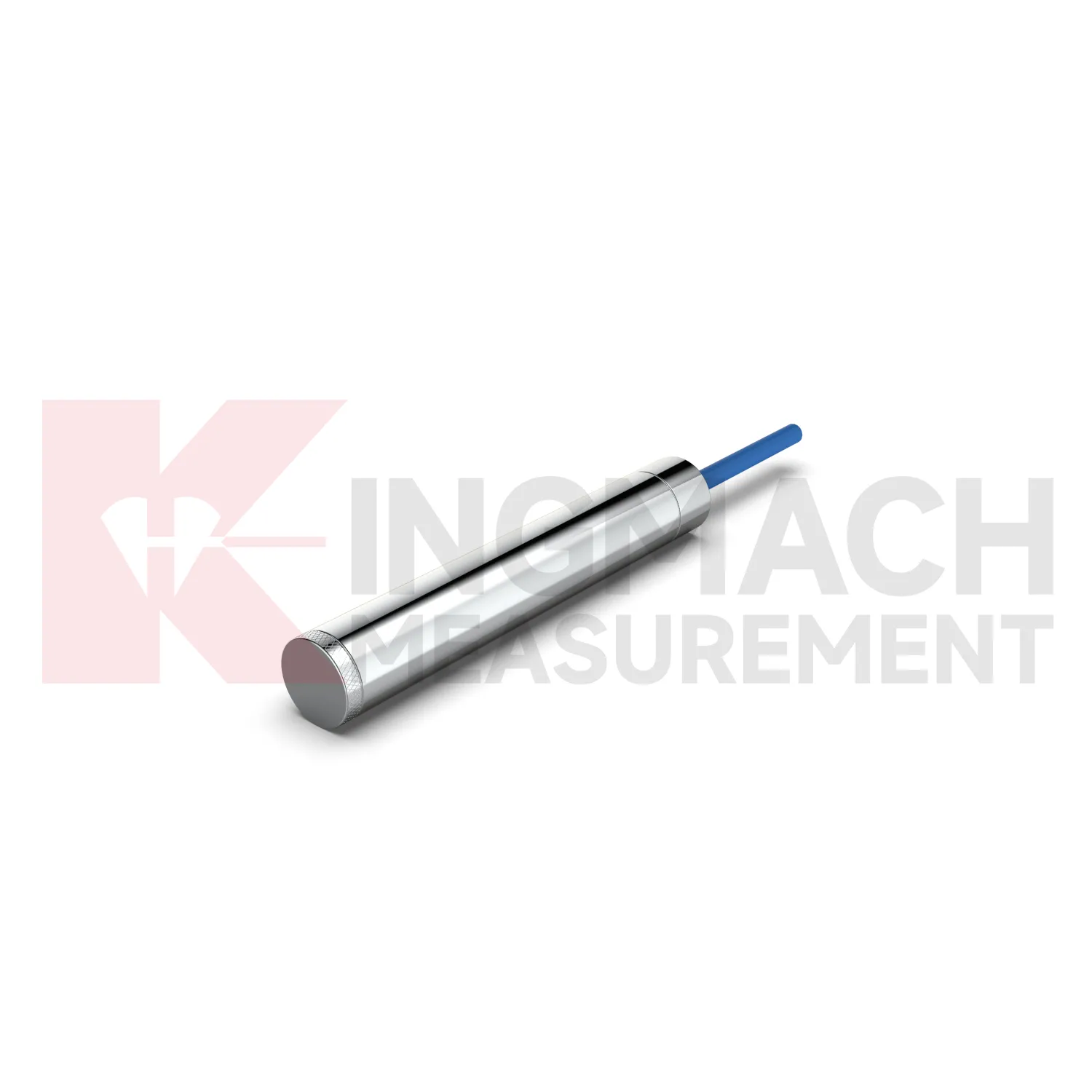
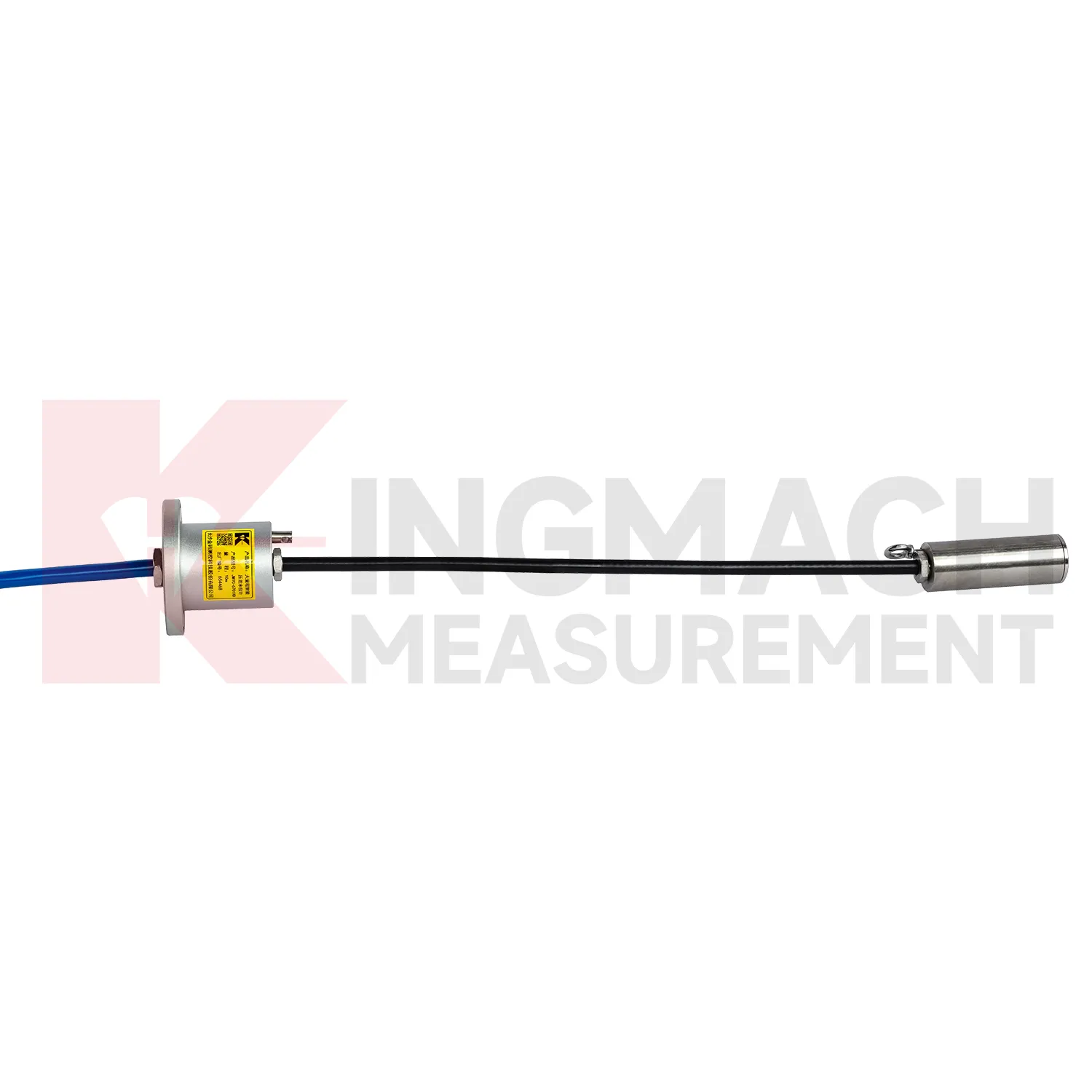
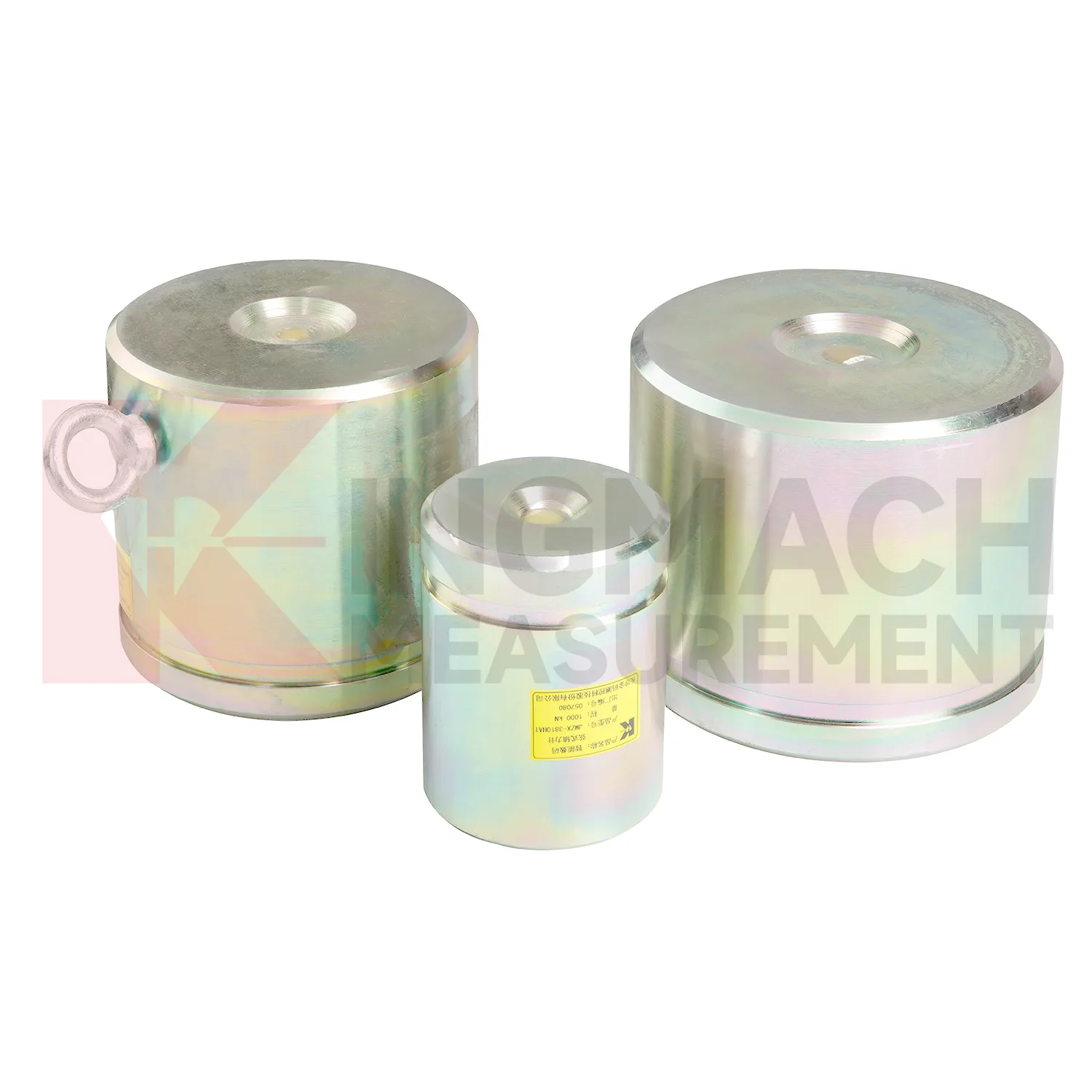
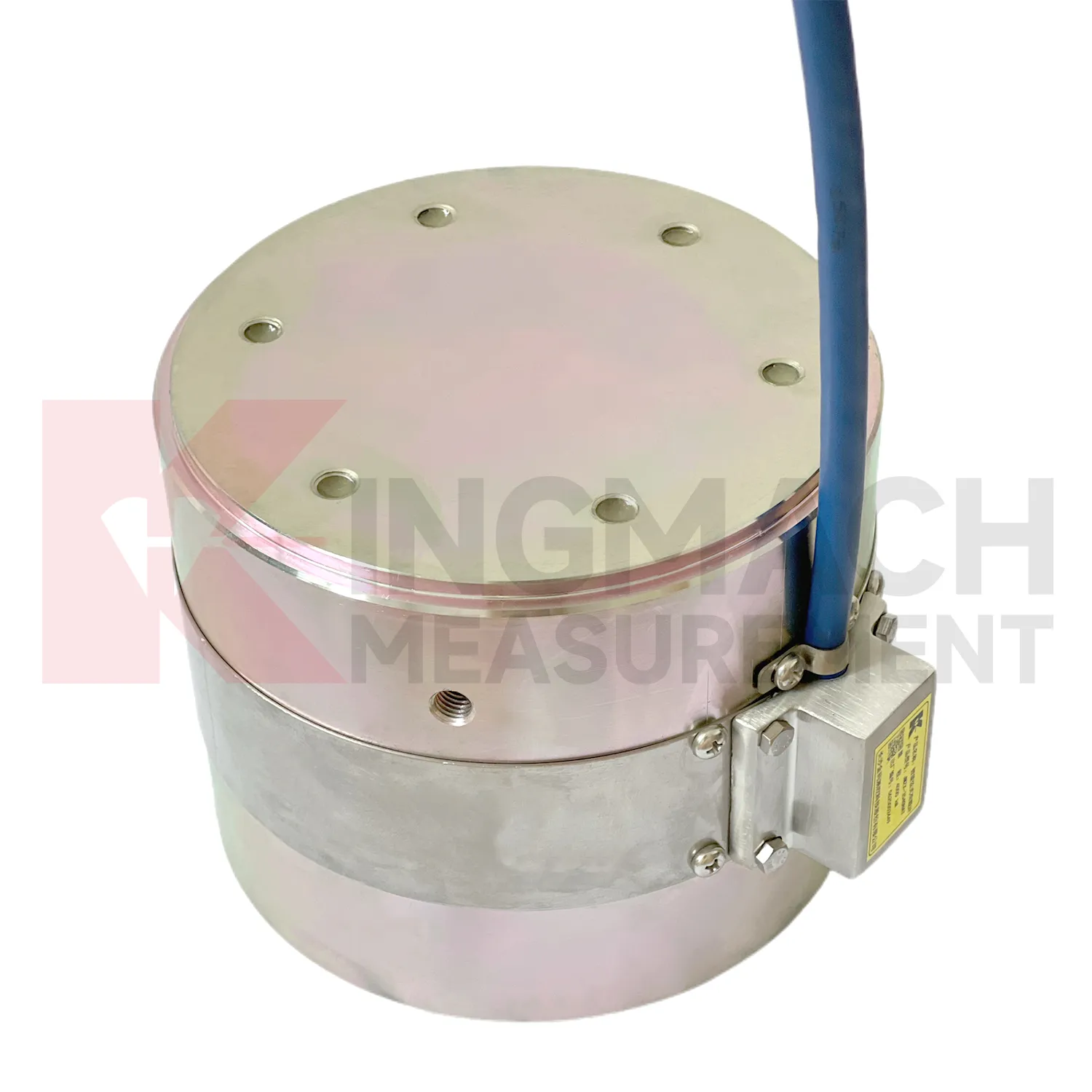
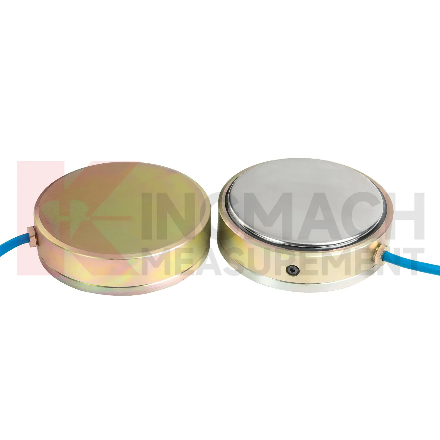
Kingmach load cell connection diagram for axial force monitoring addresses a common site problem: steel supports in deep foundation pits and tunnels can gain load quickly as excavation progresses. The JMZX-38XXHAT axial force load meter is listed in 200 kN, 500 kN, 1000 kN, 2000 kN, and 3000 kN ranges, with 0.1 kN or 1 kN sensitivity and 0.5%FS accuracy. Its product page lists a 1 MPa waterproof rating, automatic temperature correction, imported high strength steel wires, and direct axial force display in kN rather than only vibrating wire frequency. Claw type installation accessories are provided to help field placement. These features make the product relevant for temporary support monitoring, tunnels, tailings ponds, bridges, buildings, railways, transport, hydropower, and dams. Kingmach also notes that many axial force meters are customized, with model, range, and dimension confirmed at order. That matters when the support diameter, bearing plate thickness, and available clearance are already fixed by the construction design. The brand information also points to practical supply details, including Changsha origin, project use across transport and hydropower works, readout compatibility, and packaging for precision sensors. For engineering buyers, these details help connect catalog parameters with delivery, calibration, installation, and later service expectations.
Application of load cell connection diagram
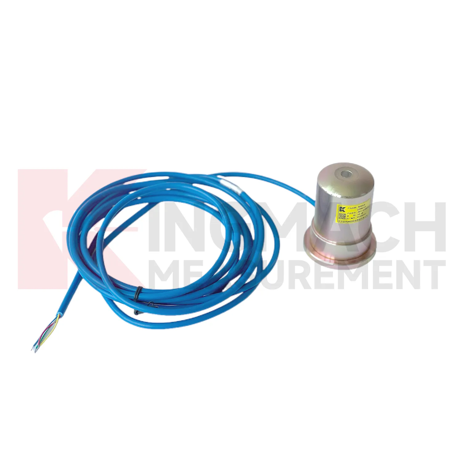
In industrial force testing and heavy equipment monitoring, load cell connection diagram can be applied to presses, jacks, lifting frames, cranes, test benches, fixtures, and custom loading rigs. The pain point is repeatability. A test may pass once, but the owner needs to know whether the next test used the same loading path, sensor range, and calibration basis. Kingmach solid load cells provide high capacity force measurement up to 10000 kN with 0.5%FS precision, while hollow load cells cover 500 kN to 8000 kN and can store 800 measurement records on smart models. Axial force meters provide 200 kN to 3000 kN ranges and direct kN display. These features suit both site acceptance testing and repeated equipment checks. Installation should control centering, bearing plate flatness, side loading, cable strain relief, and zero reading before load is applied. Data becomes stronger when the report records operator, fixture condition, load stage, temperature, and any overload event. For test benches, repeatability also depends on fixture stiffness, alignment, and loading rate. A high accuracy sensor cannot correct a poor mechanical setup, so maintenance should include the test frame and not only the measuring element. The monitoring plan should also define who reviews abnormal data and how quickly a field check must follow a confirmed alarm.
The future of load cell connection diagram
In tunnels and foundation pits, future load cell connection diagram use will move toward faster construction stage feedback. Axial force meters with 200 kN to 3000 kN ranges, 0.5%FS accuracy, direct kN display, and 1 MPa waterproofing already suit support load monitoring. The next step is pairing those readings with excavation depth, support installation time, groundwater level, wall displacement, and site progress records. LoRa or 4G gateways can reduce manual rounds where access is unsafe or work is moving too fast. Edge devices can flag missing channels, abnormal drift, or readings that changed after a cable was disturbed. This is different from a vague smart site label. It is a specific workflow where the sensor reading is checked against the work stage that should have caused it. As urban underground projects face stricter monitoring requirements, instruments that combine rugged installation, direct force output, and platform access will fit the way contractors actually manage risk.
Care & Maintenance of load cell connection diagram
Care for load cell connection diagram should separate the installation stage from the service stage. At installation, the goal is mechanical correctness: centered loading, clean contact surfaces, adequate plate thickness, no side load, no cable strain, and a documented zero reading. The JMZX-38XXHAT axial force meter has a 1 MPa waterproof rating, but connector sealing and cable protection still need field attention. Solid load cells list -30°C to 80°C working temperature and 0.5%FS precision, so records should include temperature during important readings. During service, the goal changes to trend reliability. Check whether readings shift after construction stages, heavy rain, traffic opening, reservoir level change, or support adjustment. Keep calibration documents and channel names consistent across manual and automated systems. Where smart sensors store measurement records, download or archive data before maintenance work that might disturb wiring. Most field problems can be prevented by dry connectors, protected cables, clear labels, and routine comparison with nearby monitoring points.
Kingmach load cell connection diagram
load cell connection diagram is often selected after a project team asks where force can change without being seen. In a tunnel, the answer may be the steel support. In a bridge, it may be a cable anchor or bearing. In a foundation pit, it may be a strut, anchor, or retaining wall contact zone. In a dam, it may be an anchor system affected by water level and temperature. Kingmach's monitoring product family allows these points to be linked with settlement sensors, displacement transducers, tiltmeters, piezometers, data loggers, and software platforms. That wider context matters because load change is rarely isolated. A rising force reading becomes more meaningful when it is checked against movement, pore pressure, and construction activity. A falling force reading may point to relaxation, seating loss, or damage near the bearing surface. The instrument gives the first clue, and the surrounding data explains it. It also makes abnormal values easier to discuss with designers, contractors, and maintenance teams.
FAQ
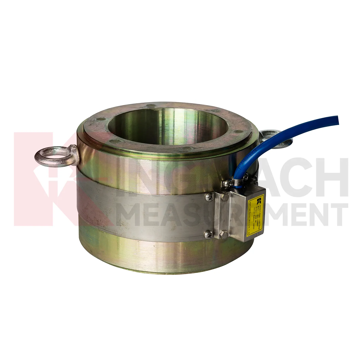
Q: How should load cell connection diagram be selected for a bridge cable or anchor point? A: Start with expected force, lock-off load, possible overload, bearing geometry, and access for later inspection. Hollow load cells are commonly used where the anchor or cable passes through the center opening. Q: What range information is available from Kingmach hollow models? A: The JMZX-3XXXHAT series is listed from 500 kN to 8000 kN, with 0.1 kN sensitivity on the 500 kN model and 1 kN on larger listed models. Q: Why does temperature correction matter? A: Cable and anchor readings can move with temperature, so built-in temperature measurement helps reduce false interpretation. Q: Can readings be stored inside the sensor? A: Smart hollow models list storage for 800 measurement records, including time, temperature, zero values, and correction data. Q: What should be checked after installation? A: Check seating, cable protection, connector sealing, zero value, first stable force, and matching channel name.
Reviews
Michael Anderson
The strain gauges and load cells are extremely accurate and stable. They performed very well in our bridge monitoring project. Highly recommended!
Christopher Martinez
Very satisfied with the readouts & data loggers. User-friendly interface and supports multiple sensor inputs.
Latest Inquiries
To protect the privacy of our buyers, only public service email domains like Gmail, Yahoo, and MSN will be displayed. Additionally, only a limited portion of the inquiry content will be shown.
Sophia***@gmail.comUnited Kingdom
Good day, we need environmental monitoring sensors including temperature, humidity, and wind sensors...
Isabella***@gmail.comGermany
Hello, we are evaluating weir flow meters for a water management project. Please share accuracy deta...